645 vga_spi_rom
645 : vga_spi_rom
- Author: algofoogle (Anton Maurovic)
- Description: Test reading/buffering/displaying SPI flash ROM data on VGA display
- GitHub repository
- Clock: 0 Hz
How it works
TBC.
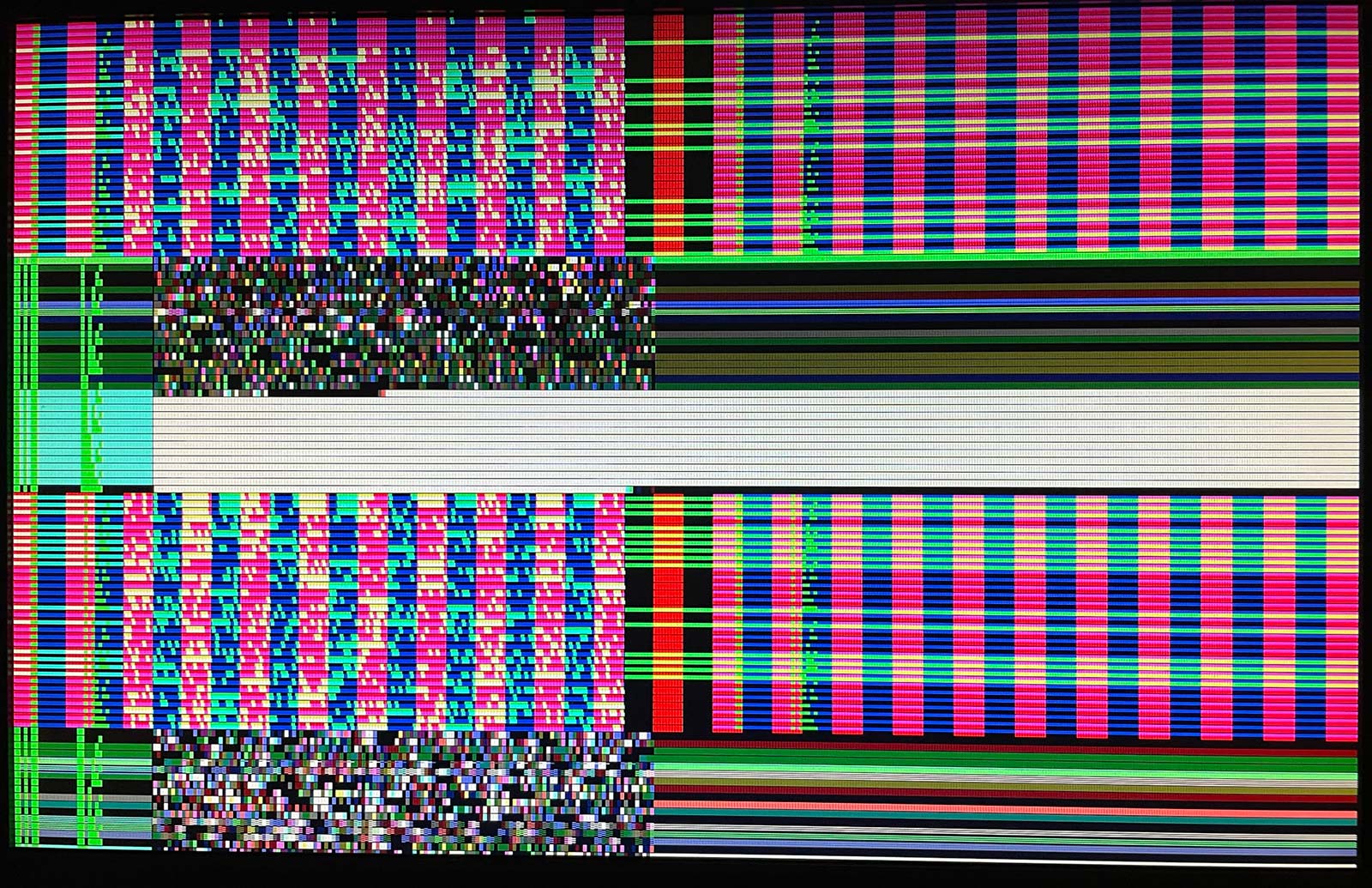
Reads data from an SPI flash ROM (or any memory compatible with, say, W25Q10 or above) and displays it on a VGA display.
Drives a display at one of two resolutions (selectable by vga_mode):
- 0: 640x480 60Hz, from 25.1750MHz clock (though 25.0000MHz should do OK).
- 1: 1440x900 60Hz, from 26.6175MHz (or as close as you can get to it).
NOTE: Some monitors will also sync 640x480 using the 26.6175MHz clock that's otherwise used for vga_mode 1... they'll get ~63Hz instead of 60Hz. That means if you can get near this frequency, you might find it to be a good middle ground that allows you to switch live between 640x480 and 1440x900. My HP L1908wm monitor works fine this way for clocks in the range of 26.3MHz to 27.0MHz, and might even work slightly beyond that.
The flash memory contents are displayed using two alternating line modes (4 lines each):
- As VGA scans near the middle of each line, read up to 136 bits (17 bytes) and store in local register memory, then display on the next scanline. NOTE: Because it buffers to memory on one line and displays the buffer on the next line, the first line is blanked out automatically by the design to avoid confusion. Hence you only actually see 3 lines for this line mode, before it switches to the next line mode.
- Just send unregistered SPI data output (MISO) directly to the VGA display. In this line mode, you should see 4 identical lines before it switches back to line mode above.
These two line modes are timed to line up, so we can check for consistency between them, but note that there is actually expected to be a slight delay in the 'MISO direct' mode because the MISO output data appears on the falling SCLK edge. At 1440x900, this should be apparent.
The reg_outs signal, if HIGH, specifies that the VGA output signals should be
registered. If LOW, the raw outputs go directly to the VGA display (inc. directly
from the SPI memory when not in a buffered line).
NOTE: This tries to use !CLK (main clock, inverted) to drive the SPI SCLK directly,
so that we don't need a faster system CLK in order to manage extra states. It keeps
this SCLK output running constantly, relying on /CS.
NOTE: Besides the main design, I've got simple loopback test:
Test_in[2:0]feeds a 3-input logicalANDwhich outputs toTest_out
It could be interesting, when we get the actual chip back, to compare inputs to outputs on an oscilloscope.
NOTE: The sync polarity of hsync and vsync will be determined by vga_mode.
How to test
TBC.
Attach an SPI memory chip with some data in it, e.g. SPI flash ROM like W25Q10. Anything that accepts a 24-bit address and supports at least 27MHz reads should be fine. I used a generic 25Q80 (8Mbit) that I pulled off an ESP-01.
Attach a VGA display:
- For simplicity, I suggest starting with 640x480@60Hz mode. To do that, strap
vga_modeto GND, and use a 25.000MHz (or ideally 25.175MHz) clock source. If you want to try 1440x900@60Hz mode instead, strapvga_modehigh and use ~26.6175MHz as your clock source. - NOTE: VGA modes 0 and 1 output different VSYNC polarity, as recommended by the spec.
- NOTE: I don't yet know what current a VGA display will sink per each input, nor what current the TT05 chip can safely supply per pin (or in total), so for now I recommend using some bigger resistors in series with each signal, even if it means an impedance mismatch. Either that, or just properly buffer each TT05 chip output with something like a 74ALVC245 (https://www.digikey.com.au/en/products/detail/texas-instruments/SN74ALVC245DWR/374035). Supposedly the Caravel IOs we're using might sink/source a max of 4mA, so assuming they're at 3.3V we could use 1kΩ resistors (which would hit 3.3mA per pin)...?
hsync,vsyncmust be connected to the display; I recommend buffering them (as above) and then a 100Ω resistor then in series with their respective VGA pins (for safe current limiting) even though 100Ω is more often done.- For a minimum display up and running quickly, attach the high bit (bit 2) of each of
red,green, andblue, each via a 1kΩ resistor, to their respective VGA colour channel input pins. It might be pretty dark, but should be safe on Caravel IO pins if you don't otherwise buffer them. - For a much better display, use an RGB222 (upper 2 bits per channel), ensuring it buffers each of those digital outputs. A good option is Tiny VGA (see: https://tinytapeout.com/specs/pinouts/)
External hardware
VGA DAC (RGB111 or 222 depth) and SPI flash memory

IO
| # | Input | Output | Bidirectional |
|---|---|---|---|
| 0 | In: vga_mode | Out: red[1] | Out: SPI /CS |
| 1 | In: rst_mode | Out: green[1] | Out: SPI io[0] / MOSI |
| 2 | In: reg_outs | Out: blue[1] | Out: SPI io[1] / MISO |
| 3 | In: N/C | Out: vsync | Out: SPI SCLK |
| 4 | In: N/C | Out: red[0] | Out: Test_out |
| 5 | In: Test_in[0] | Out: green[0] | Out: SPI /RST |
| 6 | In: Test_in[1] | Out: blue[0] | Out: SPI io[2] (/WP) |
| 7 | In: Test_in[2] | Out: hsync | Out: SPI io[3] (/HLD) |