711 Frequency counter
711 : Frequency counter
- Author: Matt Venn
- Description: measured frequency of a signal on pin 0 and displays on the 7 segment display
- GitHub repository
- Clock: 10000000 Hz
How it works
Debounces the input signal and counts how many transistions occur in a given period. A state machine then divides the count by ten by repeatedly subtracting ten and then displays the tens and units on the seven segment display.
How to test
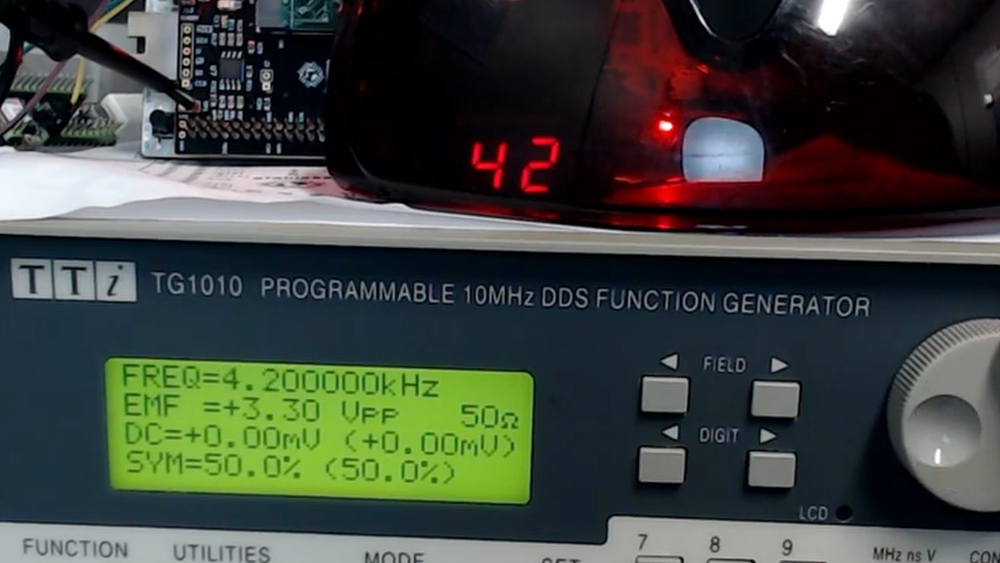
Apply a signal to the signal input and the frequency will be measured and displayed on the seven segment. The dot is used to select between display tens and units.
To change the count period (to get accurate counts), set it to match the clock frequency: clock_mhz * 100 - 1. So for a 10MHz clock, set to 999. Set the desired period (top 4 bits ui_in and all of uio_in) on the bidirectional inputs and toggle load input.
To debug, enable debug mode and check the bidirectional outputs for state machine, clock count and edge count information.

IO
| # | Input | Output | Bidirectional |
|---|---|---|---|
| 0 | signal | segment a | count period bit 07 or debug edge bit 2 |
| 1 | debug mode (on will put debug signals on bidirectional outputs) | segment b | count period bit 06 or debug edge bit 1 |
| 2 | load new period. toggle this to register the value in the bidirectional inputs | segment c | count period bit 05 or debug edge bit 0 |
| 3 | segment d | count period bit 04 or debug clock bit 2 | |
| 4 | count period bit 11 | segment e | count period bit 03 or debug clock bit 1 |
| 5 | count period bit 10 | segment f | count period bit 02 or debug clock bit 0 |
| 6 | count period bit 09 | segment g | count period bit 01 or debug state bit 1 |
| 7 | count period bit 08 | digit select | count period bit 00 or debug state bit 0 |