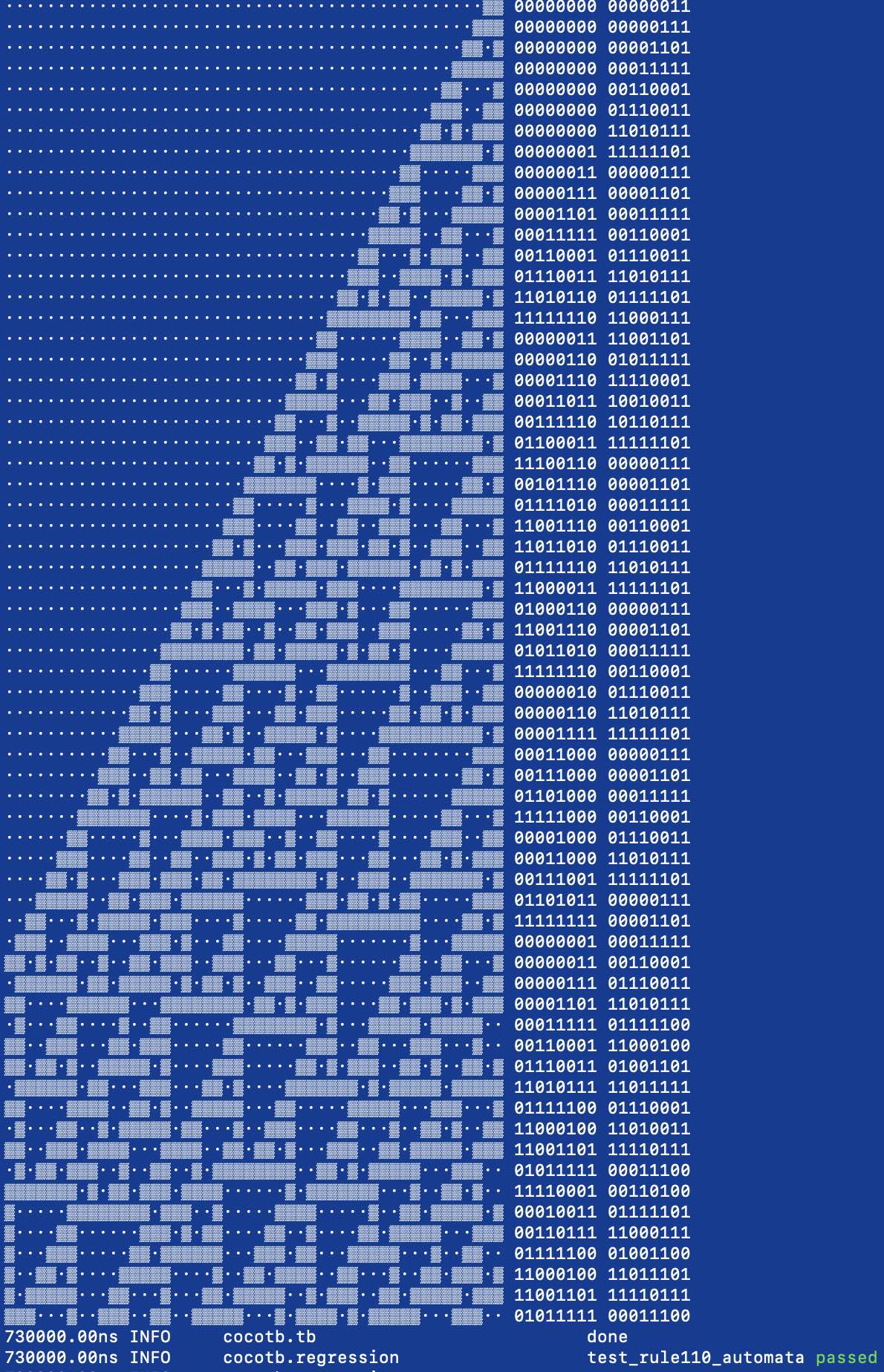
384 Rule110 cell automata
384 : Rule110 cell automata
- Author: ReJ aka Renaldas Zioma
- Description: Cellular automaton based on the Rule 110
- GitHub repository
- Clock: 0 Hz
How it works
This design executes over 200 cells of an elementary cellular automaton every cycle applying Rule 110 to all of them in parallel. Roughly 115 cells with parallel read/write bus can be placed on 1x1 TinyTapeout tile. Without read/write bus, up to 240 cells fit on a 1x1 tile!
The edge of chaos - Rule 110 exhibits complex behavior on the boundary between stability and chaos. It could be explored for pseudo random number generator and data compression.
Gliders - periodic structures with complex behaviour, universal computation and self-reproduction can be implemented with Rule 110.
Turing complete - with a particular repeating background pattern Rule 110 is known to be Turing complete. This implies that, in principle, any calculation or computer program can be simulated using such automaton!
Definition of Rule 110
The following rule is applied to each triplet of the neighboring cells. Binary representation 01101110 of 110 defines the transformation pattern.
1. Current iteration of the automaton
            111  110  101  100  011  010  001  000
             |    |    |    |    |    |    |    |
             v    v    v    v    v    v    v    v
2. The next iteration of the automaton
            .0.  .1.  .1.  .0.  .1.  .1.  .1.  .0.
Interesting links for further reading
- Elemental Cellular Automaton Rule 110
- Gliders in Rule 110
- Compression-based investigation of the dynamical properties of cellular automata and other systems
How to test
After RESET all cells will be set to 0 except the rightmost that is going to be 1. Automaton will immediately start running. Automaton produce new state every cycle for all the cells in parallel. One hardware cycle is one iteration of the automaton. Automaton will run until /HALT pin is pulled low.
The following diagram shows 10 first iteration of the automaton after RESET.
                                                      X
                                                     XX
                                                    XXX
                                                   XX X
                                                  XXXXX
                                                 XX   X
                                                XXX  XX
                                               XX X XXX
                                              XXXXXXX X
          automaton state on the             XX     XXX
        10th iteration after RESET  ---->   XXX    XX X
To read automaton state
- pull /HALT pin low and 2) set the cell block address pins.
Cells are read in 8 cell blocks and are addressed sequentially from right to left. Adress #0 represents the rightmost 8 cells. Adress #1 represents the cells from 16 to 9 on the rights and so forth.
          automaton state on the
        10th iteration after RESET  ---->   XXX    XX X
        00000000  ...  00000000000000000000011100001101
        |      |              |       |       |       |
        [adr#14]  ...  [addr#3][addr#2][addr#1][addr#0]
            cells are addressed in blocks of 8 bits
The state of the 8 cells in the block will appear on the Output pins once the cell block address is set.
Timing diagram

CLK   ___     ___     ___     ___     ___     ___           ___
   __/   `___/   `___/   `___/   `___/   `___/   `___ ... _/   `___
     |       |       |       |       |       |             |
     |       |       |       |       |       |             |

WRITE  ____                                                 _______
    X__HALT__________________________________________ ... _/

WRITE_______________  ______________  _______________
   _/ ADDR#0        `/ ADDR#1       `/ ADDR#2

READ OUTPUT_______         ________        ________
   ______/00001101`_______/00000111`______/00000000`_
              ^                ^
              |                |
       these are the expected values on
          the 10th cycle after RESET

      ____
      HALT  - /HALT, inverted halt automata
      ADDR# - cell block address bits 0..4
(Over)write automaton state
To write state of the cells, 1) pull /HALT pin low, 2) set the cell block address pins, 3) set the new desired cell state on the Input pins and 4) finally pull /WE pin low.
Cells are updated in 8 cell blocks and are addressed sequentially from right to left. Adress #0 represents the rightmost 8 cells. Adress #1 represents the cells from 16 to 9 on the rights and so forth.
Timing diagram

CLK   ___     ___     ___     ___     ___     ___           ___
   __/   `___/   `___/   `___/   `___/   `___/   `___ ... _/   `___
     |       |       |       |       |       |             |
     |       |       |       |       |       |             |
WRITE  ____                                                 _______
    X__HALT__________________________________________ ... _/

WRITE_______________  ______________  _______________
   _/ ADDR#0        `/ ADDR#1       `/ ADDR#2

WRITE INPUT_________  ______________  _____________
   __/ 00000111     `/ 11100110     `/ 11010111    `_

WRITE______  __    ________  __    ________  __    __ ... _________
           `_WE___/        `_WE___/        `_WE___/
                 wait 1 cycle    wait 1 cycle

         __
    ____ WE   - /WE, inverted write enable
    HALT      - /HALT, inverted halt automata
        ADDR# - cell block address bits 0..4
The following diagram shows 10 cycles of automaton after /HALT pulled back to high.
      [adr#14]  ...  [addr#3][addr#2][addr#1][addr#0]
      |      |              |       |       |       |
      00000000  ...  00000000110101111110011000000111
                             XX X XXXXXX  XX      XXX
                            XXXXXXX    X XXX     XX X
                           XX     X   XXXX X    XXXXX
                          XXX    XX  XX  XXX   XX   X
                         XX X   XXX XXX XX X  XXX  XX
                        XXXXX  XX XXX XXXXXX XX X XXX
                       XX   X XXXXX XXX    XXXXXXXX X
                      XXX  XXXX   XXX X   XX      XXX
                     XX X XX  X  XX XXX  XXX     XX X
10 cyles later ->   XXXXXXXX XX XXXXX X XX X    XXXXX

IO
| # | Input | Output | Bidirectional |
|---|---|---|---|
| 0 | write cell 0 state | read cell 0 state | /WE, inverted write enable |
| 1 | write cell 1 state | read cell 1 state | /HALT, inverted halt automata |
| 2 | write cell 2 state | read cell 2 state | ADDR#, cell block address bit 0 |
| 3 | write cell 3 state | read cell 3 state | ADDR#, cell block address bit 1 |
| 4 | write cell 4 state | read cell 4 state | ADDR#, cell block address bit 2 |
| 5 | write cell 5 state | read cell 5 state | ADDR#, cell block address bit 3 |
| 6 | write cell 6 state | read cell 6 state | ADDR#, cell block address bit 4 |
| 7 | write cell 7 state | read cell 7 state |